
Microscopy is much more than just 20x or 40x objectives. In this white paper, Our principal imaging engineer Markus Vartiainen dives deep into microscopy principles and theory.
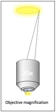
Often the first unit of measure cited in microscopy is magnification. An accustomed microscope user immediately understands the level of detail being discussed under the keywords “10×”, “40×” or “100×”. Despite its usefulness and simplicity in discussion, magnification does not indicate the resolving ability of a microscope, which depends entirely on the numerical aperture. In digital scanning microscopy, high magnification is not even preferable, because high magnification decreases the field size, which increases scanning time.
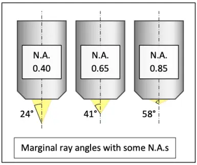
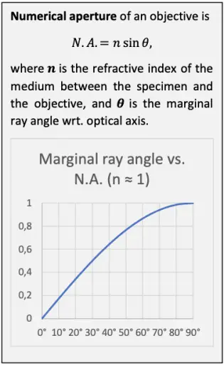
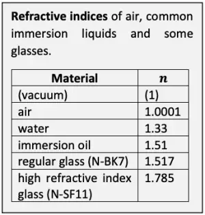
The resolving ability of a microscope system is essentially set by the objective. The theoretical maximum optical resolving ability of an objective is proportional to its numerical aperture. N.A. depends on the angle at which the objective accepts light from a single object point, and the medium between the specimen and the objective. The wider the angle and the higher the refractive index of the medium, the greater the N.A. and the better the resolving ability. In dry use, the refractive index of air between the specimen and the objective is close to 1 and thus leaves N.A. practically unaffected. In immersion use, N.A. is multiplied with the refractive index of the immersion liquid.
The number of the smallest discernible details per unit length is proportional to the N.A. Conversely, the distance between two barely discernible object points is proportional to reciprocal of the N.A.
The wavelength of light also affects resolving ability. The shorter the wavelength, the smaller the detail which can be resolved. Any optical microscope has better resolution in blue (λ ≈ 0.450 µm) than in green (λ ≈ 0.550 µm) or red (λ ≈ 0.650 µm). In practice this aspect is usually ignored, as the colors of stained samples vary greatly and must be taken as they are.
In absence of an absolute clear-cut definition of “barely discernible points”, the so-called Rayleigh criterion is commonly used. At the Rayleigh limit, the disc-like images of two barely distinct object points blend partially with each other so that they can only barely be told apart.

The disc-like shape of the image points is caused by the diffraction of light. The disc has greatest intensity at its center, and the increasingly faint ripples around the disc extend to infinity. Diffraction is a consequence of the wave-like quantum behavior of light, induced by the limiting aperture in the objective. The blending of the discs of two object points sets the limit of optical resolvability.

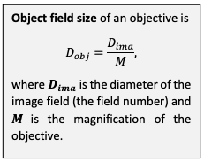
Objective manufacturers specify image field size, or field number, as the diameter of the image formed when the objective is used in a manufacturer-standard optical setup. The corresponding object field size can be calculated backwards by dividing the image field size by the magnification.
Typical image field sizes vary between 20 and 30 mm. Usually the specified field size is constant within a series of objectives with different magnifications. A 20 mm image field diameter corresponds to a 1 mm object field diameter with a 20× objective and to a 0.5 mm object field diameter with a 40× objective. Greater magnification means smaller object field.
Field size specifications are not absolute. There is no physical edge creating a black circle around the image field (unless one is caused by the limit of the illuminated field). The actual observable image may extend outside the given diameter, but its quality falls rapidly due to cumulation of optical aberrations that get gradually worse towards the image peripheral. There is no guarantee of a perfect image even inside the specified area, but the field size is a promise of useful image quality within the given limit. Field size also acts as a contract between the objective and the eyepiece in conventional microscopy.
Out of two objectives with equal N.A. and equal field size specification, the one with lowest magnification captures the largest object field. Thus, greater magnification does not mean that more information is collected – rather the opposite. With given specified field size, a combination of high N.A. and low magnification produces the greatest information density and an opportunity to cover largest object area per captured field.
A high N.A. objective has a short focal length in comparison to its physical aperture size. This increases the marginal ray angle in the object side, and thus, the N.A. Short focal length also results in higher magnification. A series of objectives is usually designed so that the optical information density in the magnified image stays relatively constant between different objectives by compensating N.A. and magnification with each other. Low magnification (large object field) is combined with low N.A., and high magnification (small object field) is combined with high N.A. The information density in the resulting magnified image is matched with the resolution of the rest of the optical system, which in conventional microscopy consists of an eyepiece and the human eye. High N.A. microscope objectives are inherently more complex than low N.A. objectives, requiring more lens elements with more demanding curvatures. Short focal length mitigates the complexity of a high N.A. objective as it allows for a smaller physical aperture and smaller lenses (by diameter), which reduces the effect of optical aberrations. Magnification is simultaneously increased, and the effective object field size is reduced. This further relaxes the requirements for the optical design of the objective.
Increasing the focal length of a high N.A. objective lowers its magnification and increases the effective field size but adds to its complexity. This, of course, is true only if the image field size remains constant, which is the case within a series of objectives from the same manufacturer, because compatibility with a specified backend system is a key driver in objective design.
Because images are two-dimensional objects, the number of fields necessary to cover a complete scanning area is inversely proportional to the square of the diameter of an individual field. Conversely, scanning time is proportional to the square root of the field diameter. Scanning speed is thus dramatically affected by the size of the individual captured fields.

Greatest scanning speed is achieved when the amount of information per captured field is maximized. The amount of information is the product of information density and field size. High N.A. objectives have the greatest information density, and low magnification objectives have the greatest field size. Thus, greatest scanning speed can be achieved with a high N.A. low magnification objective.
In digital microscopy, the base magnification of the objective should be adjusted with lenses so that the optical resolution (per the Rayleigh criterion) matches the pixel resolution of the image sensor. This way all detail resolvable by the objective is captured in the digital image. If magnification is too small, some of the optical resolution is lost due to image sensor’s inability to represent smallest details adequately. If magnification is too large, smallest discernible details are spread over more pixels than necessary. Excessive magnification leads to smaller captured object field size and slower scanning, but also bloated requirements for storage space, transfer capacity and processing power.
When magnification is set so that every pixel corresponds to a discernible detail, digital resolution can be expressed as object size per pixel. This simultaneously indicates both the resolving ability and the magnification in digital terms. If magnification is bloated, this number is bloated too and does not represent real resolving ability (although it does represent the real magnification).
In addition to proper choice of objective, magnification and image sensor, a multitude of factors affect the realized scanning speed:
• Stage movement and settling delay
• Focusing speed
• Image capture speed
• Image processing and stitching speed
• Data storage and transfer capacity
• Caching, prediction, and optimization
Scanning proceeds in a field capture cycle, where the stage is moved to a new position, focus is adjusted (if needed), and the image is captured and processed. An image captured in the previous cycle can be processed during the next cycle, which reduces idle time. Countless optimization opportunities regarding these functions emerge and must be considered.
One explicit optimization item is the image compression level. Low compression maintains details better while high compression reduces data size. A balanced setting significantly reduces the amount of data while keeping the details comparable to the source image.
The time spent from slide insertion to scan completion is not the only contributor to the practical efficiency of a digital scanning microscope. In many situations, the time from slide preparation to scan start is just as crucial as the scanning time itself. Similarly, the time to deliver the scan result to a consulting expert adds to the total delay from preparation to diagnosis just as much.
The time from preparation to scan start depends on the physical location of the scanner. A centralized scanning solution may require transport of the prepared slide and careful scan scheduling. Physical accessibility and availability can be mitigated with scanner units that can be distributed at or near the sites of action, such as surgery rooms, clinics, and remote points of care. A distributed scanning infrastructure also allows for scanning unit duplication. Scanning units can be loaded and ran as soon as slides are prepared in timing-sensitive multiple-slide use cases such as frozen section scanning.
The time from scan completion to expert diagnosis depends on the accessibility of the scanning result. Conventional microscopy requires the consulting expert to be present in person to examine the specimen, or the specimen to be sent to a central location for later examination. Digital scanning solves the postscanning accessibility problem by enabling a digital distribution of results. This allows for the expert to work in a remote location, dramatically reducing travel time and eliminating delay between scan completion and expert diagnosis.
The Grundium Ocus 40 achieves the optical resolution of a typical “40×” objective using a 0.75 NA “20×” widefield objective. A custom optical backend adjusts the final magnification to perfectly match the pixel size of a 12 Mpix image sensor, capturing all resolvable detail at 0.25 µm per pixel. A high N.A. and low magnification result in reduced scanning time while maintaining required resolving ability. The scanning time is further reduced with highly parallelized image processing algorithms which run on a multicore graphics accelerator. Stitching quality is increased using a novel patented software algorithm. The image compression rate can be adjusted to meet the demands of various use-cases.
The Ocus 40 is mechanically designed to be truly portable, and it can be relocated without recalibration. The device is self-contained yet connected, including an operating system, a processing unit and a Web user interface. Connected to the Grundium cloud, digital access through Internet is possible from anywhere in the world. Versatile and cost-effective, the Ocus 40 can be deployed right at the operative site, eliminating the delay between slide preparation and scanning. Operation, local or remote, only requires a Web browser, enabling a new era of telepathology.
The resolving ability of a digital scanning microscope relies on numerical aperture (N.A.) of the objective. A low nominal magnification is preferable for greatest field size. Final magnification is subject to the characteristics of the image sensor and needs to be corrected with custom optics. A high N.A. low magnification objective costs more but multiplies the effective scanning speed without sacrificing optical resolution. The total time from preparation to expert diagnosis depends not only on the scanning speed but local availability of the scanning device and a remote availability of the scanned image. Robustness, mobility, and connectivity are important factors for practical usefulness. The Grundium Ocus 40 uses 0.75 NA 20× high power widefield objective, state-of-the-art parallel processing digital hardware and innovative software algorithms in a compact and truly mobile design.
Markus Vartiainen
Principal Imaging Engineer
Grundium
